STEP file to G-code automatically: what actually has to happen
You cannot convert a STEP file into G-code directly. A STEP file describes the finished shape of a part; G-code tells one specific machine how to move one specific tool. Getting from one to the other automatically means doing, in software, the six things a CAM programmer does in their head: recognise the features, read the drawing, plan the setups, choose tools and strategies, post-process for the control, and verify the result before anyone presses cycle start.
Below is what each step involves, using a public test part from the US National Institute of Standards and Technology (NIST), run through KinetiCAD.
The six steps
1. Recognise the machinable features
The model arrives as surfaces. Software has to find the holes, pockets, slots, bosses, faces and chamfers in those surfaces, and work out their sizes, depths and directions of access. Getting a measurement wrong here (a slot read as a pocket, a hole diameter off by a fraction) breaks everything downstream, so this is where most of the engineering goes.
2. Read the drawing, not just the model
Tolerances, fits such as H7, surface finish, thread callouts and notes usually live on the 2D drawing, not in the STEP file. A ±0.01 mm bore needs a different tool and sequence from a ±0.2 mm clearance hole of the same size. KinetiCAD reads the PDF drawing alongside the model for this reason.
3. Plan stock, workholding and setups
Which face goes down first? Does the part fit the vise? How many setups, and on which machine: a lathe first, then a mill? A good plan minimises setups while keeping every feature reachable.
4. Choose tools, strategies and cutting data
This means picking tools from what is actually in the machine's magazine, choosing a strategy per feature (facing, adaptive roughing, finishing, drilling, chamfering), and setting speeds and feeds for the material.
5. Post-process for the control
The same toolpath becomes different code for a Fanuc, a Haas, a Siemens or a Heidenhain control. The post-processor handles that machine's format, cycles and limits.
6. Verify before release
The program is simulated against the stock, and the simulated part is compared with the CAD model: material left behind, material cut that should have stayed, collisions. A person approves before it runs.
A worked example: NIST test part FTC-09
NIST publishes a set of test models and drawings, the MBE PMI test cases, that anyone can use. FTC-09 is a 3 mm aluminium plate with holes, slots and a large rectangular cutout.
KinetiCAD planned it for a 3-axis vertical machining centre and generated a program with 17 operations and 11 tools. Here is the top of that program (only the machine name removed):
O10000 (KINETICAD GENERATED -- 3-AXIS VMC)
(MATERIAL  : Al 6061-T6 -- DEFAULT PICK, NOT CONFIRMED: CUT DATA FOR AN UNKNOWN MATERIAL, THE LOWEST OF ALL MATERIAL GROUPS -- NO PAST JOBS OF THIS SHOP ON FILE)
(STOCK     : 279.4 X 190.5 X 3.0 MM)
(G54 ZERO  : X0=LEFT  Y0=FRONT  Z0=TOP FACE)
(WORKHOLDING WARNING: setup 1: part exceeds vise capacity and the face-milled top excludes fixed toe clamps — operator must stage-clamp)
(OPS       : 17)
(OPERATOR: LOAD T48 O50.0MM Ø50 5-flute Face Mill [Al] — NOT IN MAGAZINE)
Two things in that header matter more than the toolpaths:
- It says what it doesn't know. No material was given, so it picked conservative aluminium cut data and says so, instead of silently guessing.
- It flags what a person must do. The plate is wider than the vise, so the program tells the operator to stage-clamp, and it lists the tools that are not in the magazine yet.
Then the program is simulated and the result compared with the CAD model in six projections:
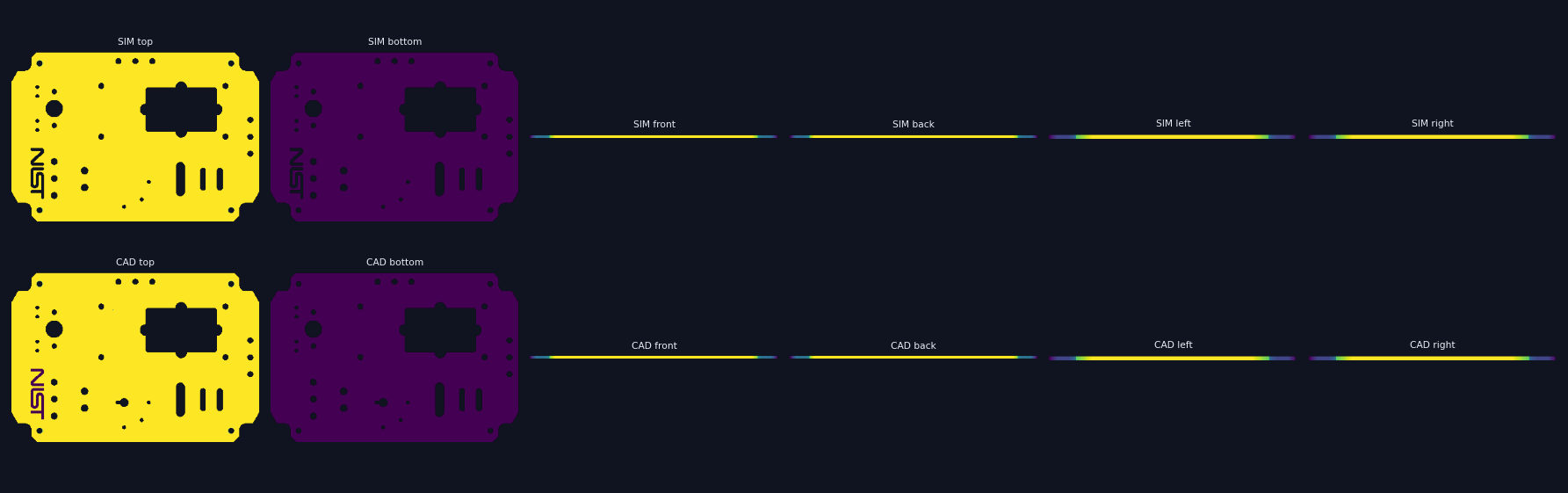
Top row: the simulated part. Bottom row: the CAD model. They match, which is what the release gate checks before an operator approves the program.
Not every test part comes out this clean. Across the NIST models we run, one is a laser-cut and bent sheet part we don't cover, and some still come out partially right: a pocket left too shallow, or stock left in a corner. That is why a person releases every program.
What to ask any vendor promising "STEP to G-code"
- Does it read the drawing, or only the model?
- Does it plan for your machines and the tools in your magazines, or a generic machine?
- Does it handle lathes, or only milling?
- Does it run inside a CAM system you must own, or standalone?
- How is the program verified, and who signs off?
- Is the G-code written by a language model? (Ask how it is checked.)
Related: AI CAM software in 2026, compared · CloudNC alternative
The NIST MBE PMI test models are published by NIST for public use. Results shown are from KinetiCAD's alpha pipeline, November 2026.
Frequently asked questions
Can you convert a STEP file directly to G-code?
Not directly. A STEP file describes the finished shape; G-code describes how a specific machine should move a specific tool. In between, software has to recognise the machinable features, choose stock, workholding, setups, tools, strategies and cutting data, generate toolpaths, post-process them for the machine's control, and verify the result.
Is there free software that turns STEP into G-code?
Free and hobby CAM tools can generate toolpaths from a STEP model, but a person still chooses operations, tools and parameters. Fully automatic generation for production parts is what AI CAM tools such as CloudNC, Toolpath, Limitless, up2parts and KinetiCAD work on, with different amounts of automation.
Why does the 2D drawing matter if I have the 3D model?
The drawing carries what the model often doesn't: tolerances, fits, surface finish, threads, and notes about which faces matter. Those change the strategy, the tool and sometimes the machine. A program planned from geometry alone can produce the right shape with the wrong tolerance.
Should a language model write G-code?
We don't think so. In KinetiCAD, toolpaths come from deterministic strategy generators and are simulated against the model before release; no language model writes the NC.